<< First [Prev] [Next] Last >> 1 2 3 4 5 ..6.. 7 8 9
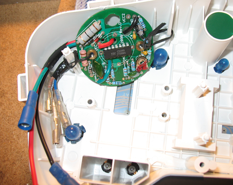
The Sunpro PCB has to be positioned so that it doesn't interfere with the support plate, doesn't block the light bulbs and close enough to the motor that it is going to be driving. I found the following positing to be most accommodating of these factors.
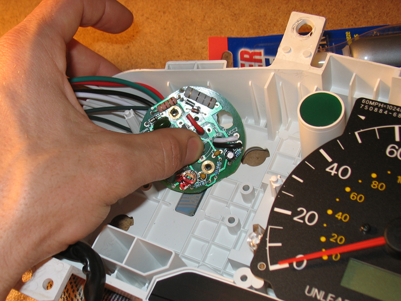
I decided to wire the motor to the PCB via 4 connectors so I can have shorter wires that I can connect to each other after putting the parts in place.
I could've used longer wires and permanently soldered them to the PCB and motor, but then I'd have too much wire to tuck in and risk obstructing the light bulbs.
I regret not using for this purpose a 4-terminal connector from a computer power supply, it would've made a nice "harness."
The most crucial part to this step is to make a note of which wire from the PCB matches which wire from the motor. You must also decide on where the
connection point of these will be and "comb" the wires in this direction while soldering them; that way they'll be under less stress.
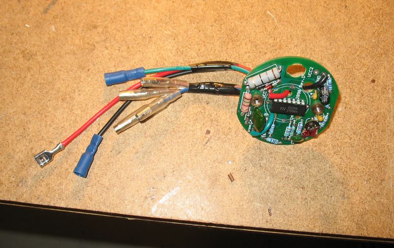
I trimmed the PCB red/black/green wires short and added connectors to them. I also added wires and connectors to the fabricated support plate tin terminals. Pretty straightforward.
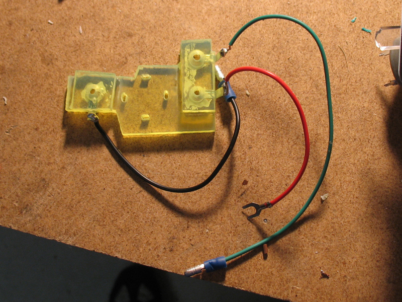
Notice how the wires sets were soldered and "combed" towards each other.
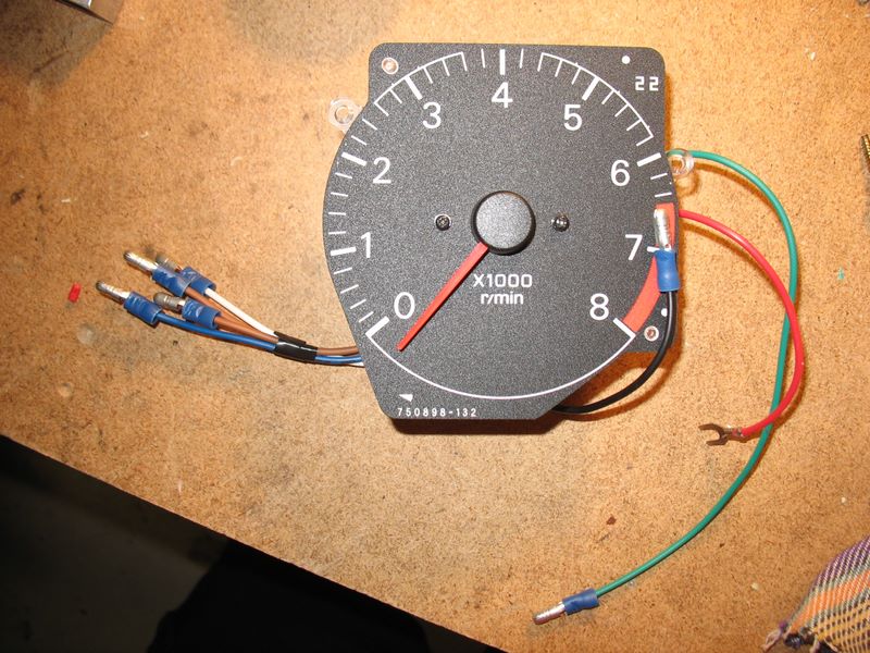
After many considerations I decided to use a pair of sturdy wire ties to hold the PCB in place. I tied one side to a dial support post. For the other I drilled a small hole in the the white cluster housing, wore the wire through and twisted it tightly. I then squeezed the wire a bit to tighten it some more.
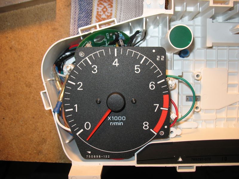
I glued the motor to the support plate and installed the tachometer assembly on the screw posts.
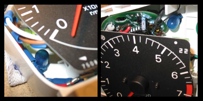
Clearance for the light bulbs
<< First [Prev] [Next] Last >> 1 2 3 4 5 ..6.. 7 8 9
To Step 7 - Moving the Odometer