<< First [Prev] [Next] Last >> 1 2 3 ..4.. 5 6 7 8 9
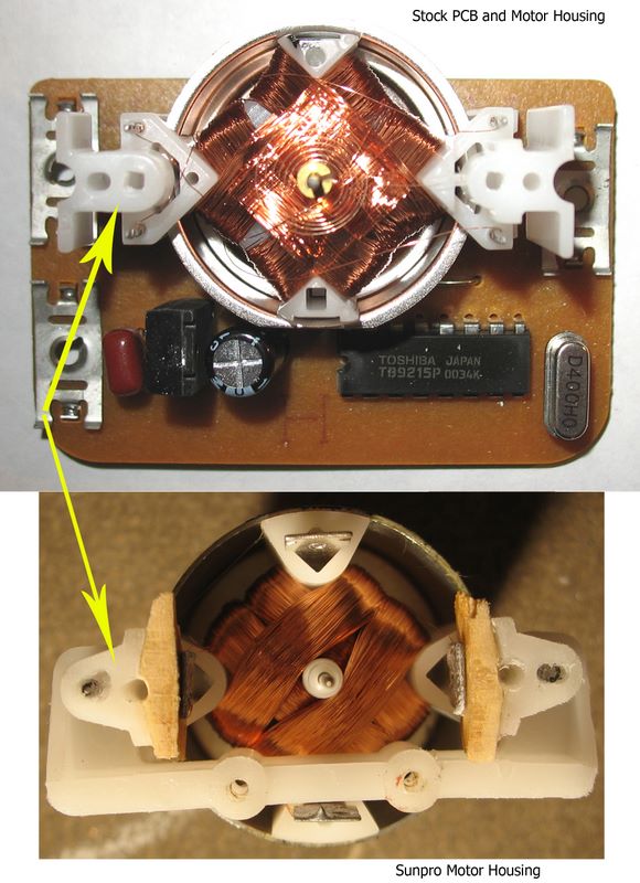
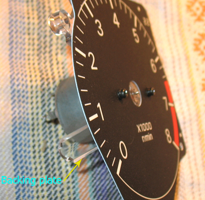
The clear dial backing plate has two alignment feet that need to go into the donor motor's housing. The plate also has the two screw holes. These two elements - the feet and the holes - have to be functional with the new motor's housing.
Luckily there are two holes in the Sunpro motor's housing that match the feet, so I simply enlarged those. But there was no room in the housing to drill complete holes for the screws. I had to patch the area between the armature posts and the plastic housing with some soft wood and superglue. Then I drilled into this extension. It's not very durable, I'm sure there may be better patching alternatives.

After this adjustment of the donor motor housing the tach's backing plate screwed very nicely in it and the dial went on top of it.

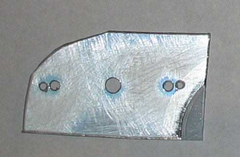
I used this template made from a CD to help with the adjustment.

The Sunpro axis is thinner than the hole in the tach's needle. To fix this, I split a single copper strand from automotive copper wiring and inserted it in the hole of the needle. Then the needle fit very well on the axis, with enough clearance from the dial.
Because the Sunpro motor housing doesn't fit well with the tach's backing plate, I had to put it on upside down. If you get in this situation keep it in mind and wire everything correctly.
<< First [Prev] [Next] Last >> 1 2 3 ..4.. 5 6 7 8 9
To Step 5 - Fabricating the Support Plate