The Sunpro Donor Tach
<< First [Prev] [Next] Last >> 1 ..2.. 3 4 5 6 7 8 9
Connect the Sunpro Tach
First, connect a test wire into your car's tachometer output and fling it over the passenger door's hinge and into the salon. Connect the tach's green wire to this wire.
Connect the black and red wires to a ground and power output, preferrable through a fuse. I have a ground and power "outlet" from my power locks installation so I plugged these wires into it.
Locate the cylinder number switch and make sure it's set for a 4 cylinder engine.
Clamp the tach somewhere handy where you can see the speed and rpms at the same time. Let the fun begin!
Sampling the RPMs
You want to write down several rpm readings as you speed up to or cruising at various speeds; basically ensure your foot is on the gas during the procedure. These records will serve you well in the later steps.
Here are the tests I did:- Cold idle rpms
- Closed-loop idle (in neutral at an intersection, no AC running)
- 1st gear at 20 and 30 mph
- 2nd gear at 20, 30, 40 and 50 mph
- 3rd gear at 30, 40, 50, 60 and 70 mph
- 4th gear at 40, 50, 60, 70 and 80 mph

Disassemble the Tachometer
Screwdriver time - to open the tach follow the manual instructions for changing the tach's light bulb. Untwist the bezel, pop out the glass and feed the wires through the housing. Put these parts aside.


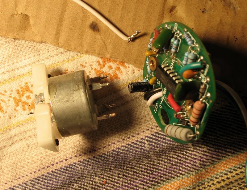
Unsolder the Motor from the PCB (printed circuit board. Ok "the brain")
Make a note of the which side is up and which is down and remove the tach's needle. You may need a pair of needle pliers to hold the motor axis in place for this procedure. Twist the end of a copper wire into a "sponge" to absorb the melted solder and unsolder each foot and squeeze it out a bit. Let it cool and move to the next foot. I had to melt each connector about 6 times before I could separate the motor from the PCB.

<< First [Prev] [Next] Last >> 1 ..2.. 3 4 5 6 7 8 9
To Step 3 - Testing and Separating the Motor

