<< First [Prev] [Next] Last >> 1 2 3 4 ..5.. 6 7 8 9
The stock PCB removed in the previous step was the part that enabled the tacho assembly to be screwed to the cluster. In this step I fabricated a part that will serve the same purpose.
The support plate is an intermediate element that allows the tacho dial and motor to be screwed to the cluster using the original screws. It has to rest on the original 3 support pillars, must conduct the electrical signals from the screws and... it has to be spot on to align the dial with the bezel correctly.

I went to a local store called Tap Plastic in San Mateo, CA and picked up some scrap plastic that would've cost more to bill for than just give it to me for free. After about three attempts I finally made a plate from it that had the motor and pillar holes in approximatively the right spot.

I had to trim it a bit so that the dial backing plate and the Sunpro PCB can fit around it.


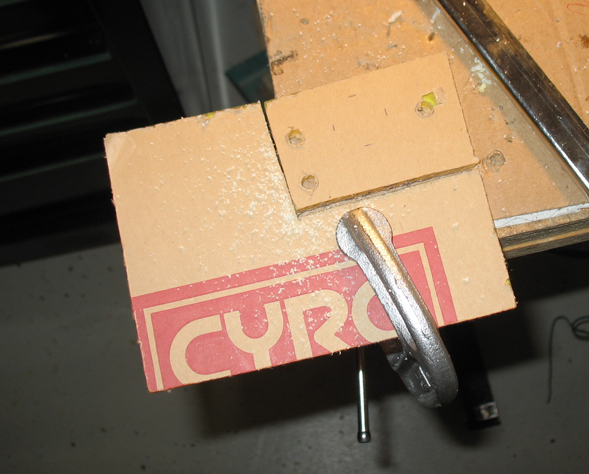
However, the motor is too tall and when I inserted it in the plate the tacho was sticking out too much. I had to make the holes wider and sink the plate down. I now had to glue extra plastic over the holes to make it reach the level where the screws can screw into it and hold it in place.
I made 2 extension caps for the purpose described above. A small one for the ground (-) screw and a big one that match the 2 screws that are close together.


The caps were glued on top of the plate enabling it to slide lower in the screw "pillars." Below is the completed support plate with the signal screw driven in. It's the most crucial part of this conversion.

Each cap has a hole halfway drilled through it so it can wear on the support pillar and reach the main plate. In the center of the hole there's a smaller hole through which the screw goes. On one side of the cap I filed a 1/4" wide strip on which I glued a tin terminal. The terminal contacts the screw and conducts the signal coming through it to the corresponding Sunpro PCB terminal. It is also something that the screw can slightly bend and fasten to and thus provide a "wedging" effect for extra support.

<< First [Prev] [Next] Last >> 1 2 3 4 ..5.. 6 7 8 9
To Step 6 - Soldering and Terminal Work